Week 2 - Transport and application layer
Important Readings
CUBIC: A New TCP-Friendly High-Speed TCP Variant
https://www.cs.princeton.edu/courses/archive/fall16/cos561/papers/Cubic08.pdfLinks to an external site.
Book References
Kurose-Ross (Edition 6): Sections 3.1.1, 3.2, 3.3, 3.4, 3.5.5, 3.6
Peterson Section 6.3
Optional Readings
Congestion Avoidance and Control
https://ee.lbl.gov/papers/congavoid.pdfLinks to an external site.
A Protocol for Packet Network Intercommunication
https://www.cs.princeton.edu/courses/archive/fall06/cos561/papers/cerf74.pdfLinks to an external site.
End-to-End Internet Packet Dynamics
https://people.eecs.berkeley.edu/~sylvia/cs268-2019/papers//pktdynamics.pdfLinks to an external site.
Data Center TCP (DCTCP)
https://people.csail.mit.edu/alizadeh/papers/dctcp-sigcomm10.pdfLinks to an external site. (Links to an external site.)
TIMELY: RTT-based Congestion Control for the Datacenter
https://conferences.sigcomm.org/sigcomm/2015/pdf/papers/p537.pdfLinks to an external site.
Design, implementation and evaluation of congestion control for multipath TCP
https://www.usenix.org/legacy/events/nsdi11/tech/full_papers/Wischik.pdfLinks to an external site.
Sizing Router Buffers
https://web.archive.org/web/20210120232627/http://yuba.stanford.edu/techreports/TR04-HPNG-060800.pdfLinks to an external site.
Transport layer summary
During encapsulation the Application layer parses the Transport layer a message. It appends some headers to make into a segment. This then gets parsed to the Network layer to make a best effort of delivery. The purpose of the Transport layer to bridge the gap between the Network layers best effort delivery and something more reliable for the application to depend upon.
The two main protocols here are UDP and TCP. These both offer the application different payoffs. Currently TCP is the most dominant out of these and is pretty ubiquitous in the internet.
Multiplexing
Multiplexing
Link to originalMultiplexing
Multiplexing is the process by which multiple applications on the same host communicate with different hosts at the same time. Multiplexing gaurentees each application only gets the messages related to communications they have made. This is done by the use of ports - an additional address system on top of IP addresses.
There are two types of multiplexing, connection orientated multiplexing and connection-less multiplexing. Connection here refers to an agreed way to and stop a communication.
Port
Link to originalPort
A port is just a number that the host associates to an application. Ports break down into 3 groups
- 0-1023 are well known ports,
- 1024-49151 are user or registered ports, and
- 49152-65535 are ephemeral ports.
Well known ports are used for system processes and protocols. For example port 80 is used by webservers for HTTP.
Registered ports are used for user applications that need a port to work off of.
The ephemeral ports or dynamic ports are used for private or temporary uses for example to connect to a web browser and receive a web page.
UDP
User Datagram Protocol (UDP)
Link to originalUser Datagram Protocol (UDP)
/../../images/udp-header.png) This tends to be used in applications that are latency sensitive or have small number of messages to send.
This tends to be used in applications that are latency sensitive or have small number of messages to send.Checksum in layer 4
Checksum in layer 4
To compute the checksum for a layer 4 header (either TCP or UDP):
- You first construct the header with an all zeros Checksum.
- Then you append the pseudo-header to the message.
- You break the message down into 16-bit segments potentially adding 0’s if needed.
- Then compute the ones complement addition off all segments. If this is all 0’s it is sent as all 1’s. An all 0 header means that the checksum was not computed.
- Fill this in as the checksum component. (Now if you perform the ones complement addition of all the 16-bit segments you should end up with all 1’s.)
- Strip the pseudo-header off the segment.
To verify the checksum on the receivers end they simply need to add all 16-bit segments and check it results in all 1’s. This makes it robust to a single bit flip whilst also being robust to most double bit flips if this happens in the same position in the 16-bit segments it will not be noticed.
Link to original
Pseudo-header
Link to originalPseudo-header
The Pseudo-header is amended to the layer 4 segment to compute the checksum. This is not sent with the layer 4 segment so has to be reproducible on the receivers side. The pseudo-header contains the source and destination IP address (found in the layer 3 header), the protocol used at layer 4 (which can be determined by the header fields) and the size of the layer 4 Segment.
This breaks the independence of the layer 3 and layer 4 headers and means you can’t change the layer 3 header without updating the layer 4 header. This exists for historic reasons - when TCP and IP where one protocol.
Ones complement
Link to originalOnes complement
The ones complement of a binary number is obtained by flipping 1’s and 0’s. Therefore if you were to add a number with its one complement you would end up with a number of all 1’s.
One’s complement addition is handled just like normal but you carry ones that would overflow to the first position. i.e. 10 + 10 = 01.
One’s complement subtraction is handled similarly but you borrow from the end digit when required.
TCP
Transmission Control Protocol (TCP)
Transmission Control Protocol (TCP)
The transmission control protocol is a layer 4 protocol that allows for multiplexing and a duplex communication channel. It is defined in RFC793. This is a connection orientated protocol which establishes a connection with TCP 3 way handshake and closes connections with the TCP connection teardown. This gaurentees the following features.
- reliability: every message will be received and acknowledge or it will be redelivered,
- ordered delivery: messages have a sequence number and will only be parsed to the Application layer in order,
- error checking: Checksum in layer 4,
- Transmission control in TCP:
- Flow control: allow the receiver to dictate how many message it can buffer.
- Congestion control and fair usage: will use connection probing to determine a safe and fair transmission rate.
The TCP header has the following fields:
- Source port,
- Destination port,
- sequence number: the sequence number of the first data octect, this has a special role in the TCP 3 way handshake,
- Acknowledgement number: the next sequence number the receiver is expecting to get,
- Data offset: the number of 32 bit words in the TCP header,
- Reserved: set to all 0’s,
- control bits: these are 0 or 1 for the following 6 fields Urgent, Acknowledgement, Push, Reset, Synchronise, and Finish.
- Window: The number of data octets number of data octets the sender of this segment is willing to receive.
- Checksum: Checksum in layer 4,
- Urgent pointer,
- Options, and
- Padding to make the header a multiple of 32 bits.
Flow control in TCP
Link to originalSuppose [[Host (networks)|host]] A is transmitting data to [[Host (networks)|host]] B. When this starts up [[Host (networks)|host]] B will reserve some amount of memory to buffer unprocessed packages. Lets say it can fit `RcvBuffer` bytes. Then it keeps track of `LastByteRead` and `LastByteRecieved`
/../../images/tcp_header.png)
TCP 3 way handshake
Link to originalTCP 3 way handshake
TCP starts a connection with a 3 way handshake to parse enough information to start the duplex communication:
- The connecting host sends an empty synchronise message with the SYN bit set to 1. It sets the initial sequence for the messages this host will be sending
client_isn.- The receiving host sends an empty synchronise-acknowledgement message with the SYN and ACK bit set to 1. It sets the initial sequence number for the messages this host will be sending
server_isnwith the acknowledgement header set toclient_isn + 1.- Lastly the connecting host sends an empty acknowledgement message with the ACK bit set to 1. The acknowledgement header is set to
server_isn + 1.
TCP connection teardown
Link to originalTCP connection teardown
When either host wants to end a TCP connection they follow a teardown protocol:
- The client sends an empty finish message with the FIN bit set to 1.
- The server sends an acknowledgement message for that closing message.
- After the server has closed off the connection it sets an empty finish message with the FIN bit set to 1.
- Lastly the client sends an empty acknowledgement message for that finish message. This is sent again after short delay to increase the chance that is received.
Reliable Transmission
Reliable transmission of TCP messages
Reliable transmission of TCP messages
TCP uses sequence numbers with acknowledgements to increase the reliability of messages. If a message was corrupted or not received it will resend that segment.
Automatic Repeat Request (ARQ)
Link to originalAutomatic Repeat Request (ARQ)
This is the way TCP makes messaging reliable. This uses a combination message acknowledgements and message timeouts to determine if it needs to resend a segment. The timeout is a length of time before it reseeds the message. This will need to be fine tuned by guessing the Round trip time (RTT).
The most basic implementation of ARQ stops and waits to check if the message was received.
Stop and wait ARQ
Link to originalStop and wait ARQ
This is an implementation of ARQ that sends some messages and wait for an acknowledgement before sending more. It uses a window size determined by the Transmission control in TCP. It will only send the window size worth of unacknowledged message before stopping to wait for a new acknowledgement message or the timeout window to be exceeded.
In TCP the acknowledgement header is set to be the next sequence number the receiver is waiting to get. There are different ways you can handle unacknowledged messages.
Go back N
Link to originalGo back N
This is a method of handling unacknowledged messages. When a sequence number is either skipped or timed out the send starts re-sending segments from the missing number.
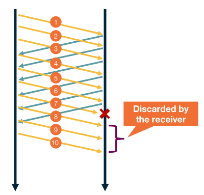
Link to originalFast retransmit
Link to originalFast retransmit
This is a method of handling unacknowledged messages. The keeps sending packages until it sees a package hasn’t be acknowledged 3 times. Then it restransmits that message before the timeout.
Transmission control
Transmission control in TCP
Transmission control in TCP
There are two main components of transmission control. These tackle two distinct problems that a connection may have:
- Flow control in TCP: Allows the receiver to control how much data gets sent to it in one go, and
- Congestion control in TCP: Allows probing of the network to guarantee maximum network utilisation without disruption to service.
These both ultimately effect the number of unacknowledged messages allowed to be sent in ARQ. This will be the minimum of the two window sizes provided by the above controls.
UDP lets the Application layer hand transmission control. Whereas TCP sees this a a widely shared feature that it can abstract away.
Link to original
Flow control in TCP
Flow control in TCP
Suppose host A is transmitting data to host B. When this starts up host B will reserve some amount of memory to buffer unprocessed packages. Lets say it can fit
RcvBufferbytes. Then it keeps track ofLastByteReadandLastByteRecieved.When returning an acknowledgement message to host A for a segment it populates the window field with
RcvBuffer - [LastByteRecieved - LastByteRead]. This informs host A how much buffer host B has left.Host A will use this as one input to its Transmission control.
Link to originalWhat if the window size is 0?
If the window size is 0 on the last Acknowledgement message then we could have a deadlock if host B doesn’t want to send anything to host A. It will process its messages but never send another ACK message to host A to tell it, it has more buffer available. To solve this problem host A will periodically send host B a single byte of data. Then it gets the new buffer size in the ACK message.
Congestion control in TCP
Congestion control in TCP
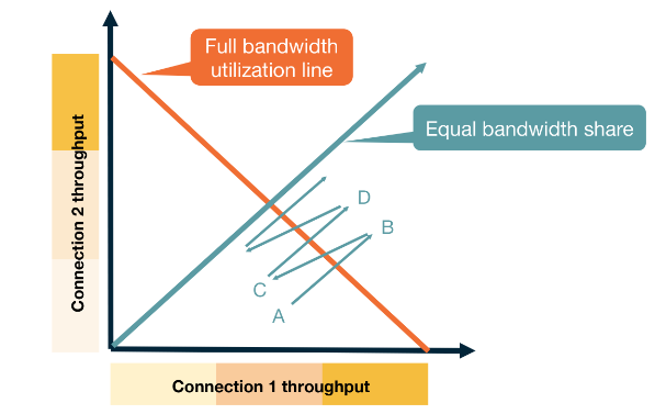
Congestion control is use to utilise the network with the following goals in mind:
- Efficiency: We should try to have high utilisation of the network at all times.
- Fairness: Each user should have a fair share of the network.
- Low delay: We should not overwhelm the switches and routers buffers causing a large delay within the network.
- Fast convergence: We want to get to a stable point that achieves all the above quickly.
There are two approaches when it comes to congestion control.
- Network assisted: You rely on the network to provide some signal about how congested it is. This could be done via:
- ICMP source quench.
- End-to-end congestion control: Hosts need to infer congestion from the traffic they receive. This can use different signal such as:
- Packet delay based on acknowledgement times.
- Packet loss using the acknowledgement sequence numbers.
- Major network delay based on the time out window.
TCP uses the end-to-end approach. It mainly uses packet loss to detect congestion as packet delay can have quite a bit of noise in the system. It uses major network delay to reset itself.
TCP uses ACK messages as a probes and adopts a probe-and-adapt approach to adjusting the window size (number of unacknowledged packets) for congestion control.
Additive increase Multiplicative Decrease (AIMD)
Link to originalAdditive increase Multiplicative Decrease (AIMD)
This is a method of probe-and-adjust that some TCP implementations use.
- Every RTT it wants to increase the window size by 1.
- If there is congestion on the network it halves the window size.
As the window size is really in bytes rather than packets and we would like incremental progress rather than waiting for a full RTT. We increment the window size using the maximum segment size (MSS) proportionally to the current CongestionWindow size on every acknowledged packet using the formula:
TCP Reno
Link to originalTCP Reno
This is the classical Congestion control in TCP. It starts the window size to be 1 packets big. It uses AIMD with two different signals.
- If a message is waited on 3 times, it halves the congestion window in AIMD.
- If it reaches a timeout window (i.e. no message is received for a given length of time). It resets the congestion window back to 1.
This however is quite slow to start. Therefore Reno implements “slow start” doubling up to some threshold. This means that while the congestion window is below the that threshold every RTT it doubles the congestion window. Once it passes this threshold or it drops a packet it switchest back to AIMD The “slow start” also takes place if we have a timeout. In this case the threshold is set to be the congestion window before the timeout.
Fairness
This achieves fairness through AIMD. As the punishment for dropping a packet is exponential vs an increase which is linear. If you are using more of the network your probability of dropping a packet is higher and equally that punishment is larger. Whilst you are not dropping packets your increase is the same as every other network participant.
This exponential vs linear dynamic allows for fast convergence to an equilibrium.
Fairness between connections not applications
If one application has multiple open connections each connection will reach a fair state but an application with many connections will have an unfair share of the network.
TCP CUBIC
Link to originalTCP CUBIC
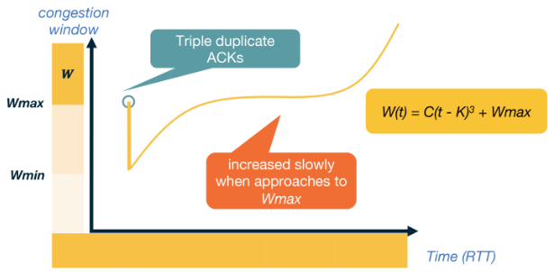
In networks with large bandwidth or a long delay TCP Reno yields low network utilisation. TCP CUBIC is the more efficient implementation used within the linux kernal. CUBIC still uses a reset for a timeout and halves when it gets a triple unacknowledged message. Though this implementation uses two different features to TCP Reno:
- A cubic polynomial increase function.
- Increase is based off the time since the last packet loss instead increasing when it gets an ACK packet.
Let
be the window size, and lets say we are given two constants and . Suppose we get a packet loss when is at and let be the time since that event. First set then we set our window size to be Throughput
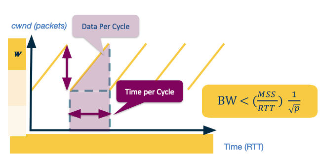
Assuming we have a probability of
of dropping a message - we can model what our expected throughput is for TCP Reno. For this model we assume the network delivers packets then drops one. This provides the following saw-tooth diagram.
Assume the max window size is
, then as the number of packets is increasing linearly we have the width and height of the saw is . Therefore the total packets sent is Which using our assumption means that
Therefore we can compute the bandwidth of this connection.
We set
to be a constant as we can study this in practice rather than just in theory. In practice we see that is regularly less than 1, so we say Data Centres
In Data Centres we see a lot of developments in TCP implementations for congestion control. There are two main reasons for this:
- Data centres make lots of delay sensitive short messages that normal TCP wouldn’t handle well.
- Data centres are owned by a single entity so they can deploy different algorithms much easier.