Week 1 - Introduction
Here are some questions you should be able to answer to start the course:
• What are the advantages and disadvantages of a layered architecture?
Modularity, Separation of concerns, and interchange of methods at different layers.
Duplication of effort, more covert coupling, and additional overhead.
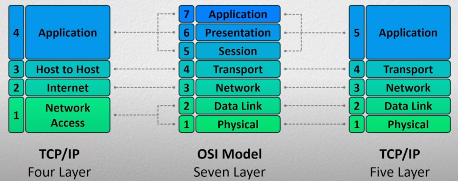
• What are the differences and similarities between the OSI model and the five-layered Internet model?
• What are sockets?Connection between OSI and IPS models
Connection between OSI and IPS models
The OSI model was originally invented when the main computers where main frames. Making layer 5 more important however in modern applications the roles and responsibilities of the last 3 layers in the OSI get very mixed and end up being combined into one in other. Some applications might not implement some of them.
For example HTTP uses cookies for layer 5, extended ASCII for layer 6, and keywords for layer 7. Whereas FTP doesn’t have a way to implement layer 5, uses the same extended ASCII for layer 6 but different commands for layer 7.
This mix of these layers is normally dependent on the protocol - so normally rolled up into one thing.
Link to original
• Describe each layer of the OSI model.Socket
Link to originalSocket
A socket is the collection of 3 bits of information:
- A transport protocol such as TCP or UDP,
- An Internet Protocol (IPv4), and
- A port.
They are used by applications to get send and receive data. This is the PO box for this application on the internet.
• Provide examples of popular protocols at each layer of the five-layered Internet model.Open Systems interconnection (OSI) model
Link to originalOpen Systems interconnection (OSI) model
The OSI model was presented by the International Organisation for Standardisation (ISO) for how networks should be structured. Its ultimate goal is to gaurentee safe communication between two hosts that may or may not be on the same network. It has 7 layers each with a different responsibility.
- Physical layer,
- Data Link layer,
- Network layer,
- Transport layer,
- Session layer,
- Presentation layer, and
- Application layer
This separation allows for scalability, molecularity and flexibility to add or remove components. Though comes with some down sides such as
- Some layers’ functionality depends on the information from other layers, which can violate the goal of layer separation.
- One layer may duplicate lower-layer functionalities. For example, the functionality of error recovery can occur in lower layers but also in upper layers as well.
- Some additional overhead that is caused by the abstraction between layers.
HTTP TCP ARP • What is encapsulation, and how is it used in a layered model?
• What is the end-to-end (e2e) principle?Encapsulation
Link to originalEncapsulation
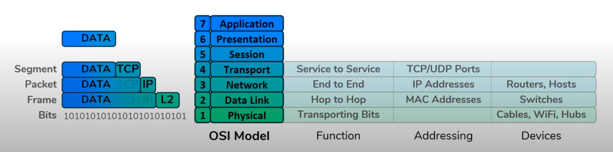
Once an application has generated some data encapsulation is the process of wrapping that data with headers so it can traverse through the internet to make it to it’s destination.
Layer 4 takes the data and adds the source and destination ports to the data to make it a segment.
Layer 3 takes the segment and adds a source and destination Internet Protocol (IPv4) to make it a packet.
Layer 2 takes the packet and adds a source and destination MAC address to make it a frame.
This is moved onto layer 1 to be passed along to its destination.
The reverse process is called de-encapsulation.
• What are the examples of a violation of e2e principle?End to end principle
Link to originalEnd to end principle
The end to end principle states that certain functions in a network, such as error correction or data integrity, are best implemented at the endpoints (source and destination) rather than in the intermediary nodes (like routers and switches). This ensures more efficient and reliable communication by minimizing the complexity and potential points of failure within the network.
For example TCP handles error checking, data re-transmission, and flow control but this is handled in the application layer rather than within the switches or routers.
- Network Address Translation (NAT): NAT modifies the IP address information in packet headers while they are in transit, which breaks the end-to-end connectivity and transparency. This complicates end-to-end communication protocols that rely on unique IP addresses.
- Firewalls and Deep Packet Inspection (DPI): Firewalls and DPI devices inspect and sometimes modify the content of data packets as they pass through the network. This interferes with end-to-end encryption and data integrity checks.
- Content Delivery Networks (CDNs): CDNs cache content closer to users to improve performance and reduce latency. While this benefits performance, it introduces intermediary nodes that alter the direct path between the source and destination, which can complicate end-to-end control and data integrity.
- QoS (Quality of Service) Mechanisms: QoS techniques prioritize certain types of traffic over others within the network. While this can improve performance for specific applications, it introduces complexity and control within the network itself, rather than at the endpoints.
- Proxy Servers: Proxy servers act as intermediaries for requests from clients seeking resources from other servers. They can modify requests and responses, breaking the direct communication path and potentially interfering with end-to-end data handling.
• What is the EvoArch model?
• Explain a round in the EvoArch model.
• What are the ramifications of the hourglass shape of the internet?
• Repeaters, hubs, bridges, and routers operate on which layers?
• What is a bridge, and how does it “learn”?
• What is a distributed algorithm?
• Explain the Spanning Tree Algorithm.
• What is the purpose of the Spanning Tree Algorithm?
Additional readings
Important Readings
How to Read a Paper
https://people.cs.umass.edu/~phillipa/CSE390/paper-reading.pdfLinks to an external site.
How to Read a Research Paper
https://www.cs.tufts.edu/comp/150PLD/ReadingPapers.pdfLinks to an external site.
The Design Philosophy of the DARPA Internet Protocols
http://ccr.sigcomm.org/archive/1995/jan95/ccr-9501-clark.pdfLinks to an external site.
The Evolution of Layered Protocol Stacks Leads to an Hourglass-Shaped Architecture https://www.cc.gatech.edu/~dovrolis/Papers/evoarch.pdfLinks to an external site.
Book References
If you have access to the Kurose-Ross book and the Peterson book, you can find the chapters discussed in this lecture. As mentioned in the course schedule, purchasing the books is not required.
- Kurose 1.5.1 (Edition 6): Layered Architecture
- Kurose 1.5.2 (Edition 6): Encapsulation
- Computer Networks: A Systems Approach - Edition 4, Section 3 and 3.1 (Interconnecting hosts and networks)
- Computer Networks: A Systems Approach - Edition 4, Section 3.2.1 (Learning Bridges)
- Computer Networks: A Systems Approach - Edition 4, Section 3.2.2 (The looping problem and the spanning tree algorithm)
Optional Readings
Brief History of the Internet (1997)
https://www.internetsociety.org/wp-content/uploads/2017/09/ISOC-History-of-the-Internet_1997.pdfLinks to an external site.
Rethinking the design of the Internet
https://dspace.mit.edu/bitstream/handle/1721.1/1519/TPRC_Clark_Blumenthal.pdf?sequence=1&origin=publication_detailLinks to an external site.
The End-To-End Argument
http://web.mit.edu/Saltzer/www/publications/endtoend/ANe2ecomment.htmlLinks to an external site.
http://web.mit.edu/Saltzer/www/publications/endtoend/endtoend.pdfLinks to an external site.
Internet Clean-Slate Design: What and Why?
https://citeseerx.ist.psu.edu/pdf/700ba413874b914557742ab688cf4c7a445e7c47Links to an external site.
A Clean Slate 4D Approach to Network Control and Management https://www.cs.princeton.edu/~jrex/papers/ccr05-4d.pdfLinks to an external site.
Holding the Internet Accountable
https://conferences.sigcomm.org/hotnets/2007/papers/hotnets6-final71.pdfLinks to an external site.
An Algorithm for Distributed Computation of a Spanning Tree in an Extended LAN https://www.it.uu.se/edu/course/homepage/datakom/ht06/slides/sta-perlman.pdfLinks to an external site.
Layer architecture of the internet
The internet stack is a layered stack of protocols where each layer depends loosely on the layer below and is requried by the layer above. This allows doe scalability molecularity and the flexibility to add or remove components.
The first version of this structure was the OSI model - though later refinements came about such as IPS model which combined some layers.
Open Systems interconnection (OSI) model
Link to originalOpen Systems interconnection (OSI) model
The OSI model was presented by the International Organisation for Standardisation (ISO) for how networks should be structured. Its ultimate goal is to gaurentee safe communication between two hosts that may or may not be on the same network. It has 7 layers each with a different responsibility.
- Physical layer,
- Data Link layer,
- Network layer,
- Transport layer,
- Session layer,
- Presentation layer, and
- Application layer
This separation allows for scalability, molecularity and flexibility to add or remove components. Though comes with some down sides such as
- Some layers’ functionality depends on the information from other layers, which can violate the goal of layer separation.
- One layer may duplicate lower-layer functionalities. For example, the functionality of error recovery can occur in lower layers but also in upper layers as well.
- Some additional overhead that is caused by the abstraction between layers.
This is where a lot of the popular protocols operate such as HTTP, SMTP, FTP, or DNS. This controls the application specific command.
This is responsible for converting data from its encoded format to one understood by the application. This might be as simple as converting bits to ASCII.
This is responsible for merging different transport streams that are intended for the same user. For example the audio and video streams for a call.
This is responsible for getting the data correctly from one end to another. It uses protocols such as UDP and TCP. This attaches source and destination ports to the message to make it a segment.
Note that TCP adds
- multiplexing,
- congestion control and
- reliable, in-order delivery.
Though for this is slower and more complex to implement.
The network layer is responsible for getting the data to the correct host in the internet. It wraps the Segment up with the IP addresses to make a datagram. This uses the IP to do this.
This layer uses MAC addresses and bind this to the datagram to make a frame. This is used to safely pass segment through networks.
This facilitates communicate these frames through the physical hardware associated to the network be that cables or wifi.
Encapsulation
Link to originalEncapsulation
Once an application has generated some data encapsulation is the process of wrapping that data with headers so it can traverse through the internet to make it to it’s destination.
Layer 4 takes the data and adds the source and destination ports to the data to make it a segment.
Layer 3 takes the segment and adds a source and destination Internet Protocol (IPv4) to make it a packet.
Layer 2 takes the packet and adds a source and destination MAC address to make it a frame.
This is moved onto layer 1 to be passed along to its destination.
The reverse process is called de-encapsulation.
The end hosts have to implement encapsulation and de-encapsulation however intermediary don’t need to. This is summarised by the End to end principle.
End to end principle
Link to originalEnd to end principle
The end to end principle states that certain functions in a network, such as error correction or data integrity, are best implemented at the endpoints (source and destination) rather than in the intermediary nodes (like routers and switches). This ensures more efficient and reliable communication by minimizing the complexity and potential points of failure within the network.
For example TCP handles error checking, data re-transmission, and flow control but this is handled in the application layer rather than within the switches or routers.
In simple terms this states that the network core should be simple and minimal, while the end systems should carry the intelligence. Any feature in the core of the network should be shared by all applications. Therefore there could be error checking at the physical layer if that error checking was done without needing to know the structure of the original message.
Violations of the end to end principle
Network Address Translation (NAT)
Link to originalNetwork Address Translation (NAT)
A Network Address Translation boxs are used to solve the issue of limited IP addresses on the public Internet. They present a single public Internet Protocol (IPv4) and remap internal IP addresses and ports to that Internet Protocol (IPv4) and allocate it a port. To do this these boxes maintain a mapping table. This violates the End to end principle as a host that packets pass through has to change the layer 3 and layer 4 header before it has arrived at the host.
Most home routers have a NAT in them this means your home internet will have a single Internet Protocol (IPv4) to the outside world.
Firewall
Link to originalFirewall
A firewall introspects Packets entering a network and filters packets out that are selected as malicious or unnecessary. This violates the End to end principle as introspection on the packets happens before they get to their destination. This is seen as needed to protect hosts and network integrity.
Shape of the internet
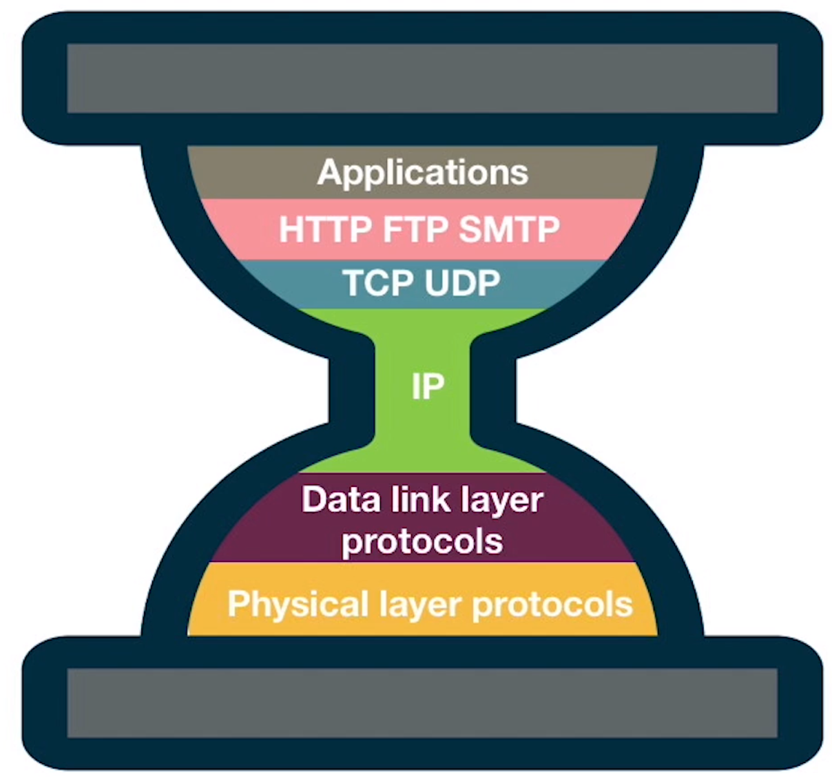
Internet protocol stack hourglass shape
Internet protocol stack hourglass shape
When you look at the number of protocols at each layer of the OSI model you notice that there is an hour glass shape. With layer 7 and layer 1 having a variety of protocols in them buts layer 3 only using a single protocol the Internet Protocol (IP). layer 4 is dominated by UDP and TCP.
Link to original
There is a model that was purposed to explain this shape.
Evolutionary Architecture model (EvoArch)
Link to originalEvolutionary Architecture model (EvoArch)
This is a model built to explain the Internet protocol stack hourglass shape. It builds a DAG in discrete time steps
over time to model the protocols in the OSI model.
- Define a set of layers
, - Each vertex
gets mapped to a layer , - Each edge
has and describes the relationship protocol can use protocol as its lower level protocol. - We define the set of parents of a node
to be substrates. - The children of node
we define to be its Product. - Each layer
has a generality probability associated to it, . This determine the probability a higher level protocol will depend on a new protocol in this layer in the future. For each where for each where then with probability . - Each node
has a value at time , , this is defined by the product of that node i.e. . - There is a competitor threshold
that defines to competitors for nodes - Nodes die if their competitors have too much value. This also kills upstream nodes if they only depended on that node for its layer.
- Nodes also get added randomly to the graph as a percentage of the total size of the current network. Though this can very depending on the implementation
To update this model we do the following steps.
- Introduce new nodes to the model.
- Going from top to bottom carry out the following for each layer
- Add new edges for new nodes.
- Calculate new values for the nodes.
- Examine nodes in decreasing value order and remove if needed.
- Stop if we reach a predetermined number of nodes.
In some set ups of this model the width of the layers tend to follow that of the internet with a similar hourglass shape. Implying there might not be anything particularly special about Internet Protocol (IP), UDP, or TCP but more there was always going to be a bottle neck here.
These protocols do defend one another for a replacement to IP to come about it would have to rival being used by both TCP and UDP.
This is good to keep in mind for development for any layered system - if you don’t want monopolies to form you need to garentee a variety of non-competing protocols at each layer.
Devices
Repeater
Link to originalRepeater
Hub
Link to originalHub
Bridge
Link to originalBridge
A bridge only has two ports but they know which devices are on either side. They will only repeat signals if the destination host is on the opposite side of the bridge. To do this a bridge maintains a forwarding table which maps MAC addresses to ports. It learns which hosts are on either side by reading the source MAC address of frames coming into the bridge.
Switch
Link to originalSwitch
Router
Link to originalRouters
Spanning tree algorithm
There is a problem with Switching when there are multiple switches that form loops. A message may go round infinitely. To get around this the switches in a network try to form a spanning tree amongst themselves so they stop infinite cycles.
Spanning Tree Protocol (STP)
Spanning Tree Protocol (STP)
The spanning tree protocol was introduced to get rid of cycles in networks that used bridges and hubs. It does this by forming a spanning tree in the network so that the layer 2 devices use to send messages through.
This is a distributed algorithm and is computed locally on each device in the network for their neighbours. Each device will have a unique ID and the tree will be formed by picking the root of the tree to be the device with the lowest ID. Then each device working out its nearest neighbour to the root of the tree.
This is done iteratively by each device telling its neighbours 4 bits of information:
- The ID of itself,
- The node it believes is the root,
- The shortest distance between itself and that node, and
- If this host thinks that node is the next node in the shortest path to the root. These messages are Bridge Protocol Data Units (BPDUs).
Once it receives a configuration message, it then recalculates what it thinks is the new root and its shortest distance to that root. It then tells all its neighbours about its new status.
To calculate the spanning tree it keeps track of which node is its next nearest neighbour to the root. It splits ties of equal distance paths by taking the path that ends in the root with the lowest ID.
To calculate the set of active connections a node keeps track of which node is the next node in the shortest path to the root and the nodes that think it is the next node in the shortest path to the root. These nodes are the nodes that are considered active links.
When broadcasting and flooding all switches still send messages to all links but a switch only forwards or floods a message it receives on an active connection.
When switches are working out the topology they do not forward regular messages.
Link to original