Week 0 - Assumed knowledge
Notes from Fundamentals course
I followed this Fundamentals course to understand the basics.
Lecture 1: Hosts and devices
Some terminology first:
Host (networks)
Link to originalHost (networks)
A host can have multiple meanings in the context of networks. Most broadly it means any actor that can send and receive traffic on a network. In the context of Internet Protocol (IPv6) it is a Node (IPv6) that is not a Router (IPv6).
Client
Link to originalClient
A client is defined in reference to any transaction. The client is the Host (networks) who is receiving data in that transaction.
Server
Link to originalServer
A Server can have multiple definitions in the context of networks. Most broadly it is just a Host (networks) that implements an Application that can server requests. However, in the context of a transaction it is simply the Host (networks) that is sending data.
Note
These terms are relative to a single request a host can be a client in another request.
Internet Protocol (IPv4)
Link to originalIP address
Subnets
Link to originalSubnets
A sub network is a prefix of an IP address normally of length 8, 16, or 24. These form the hierarchy of IP addresses.
Subnets can either be represented as an IP address followed by a slash with the prefix length such as 123.145.0.0/16. Or as an IP address with a network mask such as 123.145.0.0 with 255.255.0.0 which represents the same information.
Network
Link to originalNetwork
Internet
Link to originalInternet
Signal strength decays over long distances.
Repeater
Link to originalRepeater
When joining lots of computers together there is a scaling problem if they all need to connect to one another. So instead we us a single entity to act as an intermediary.
Hub
Link to originalHub
Bridge
Link to originalBridge
A bridge only has two ports but they know which devices are on either side. They will only repeat signals if the destination host is on the opposite side of the bridge. To do this a bridge maintains a forwarding table which maps MAC addresses to ports. It learns which hosts are on either side by reading the source MAC address of frames coming into the bridge.
Switch
Link to originalSwitch
Router
Link to originalRouters
Gateway
Link to originalGateway
The gateway for a router connected to a network is its Internet Protocol (IPv4) on that network.
Routers make the hierarchy on the internet possible by owning the prefix for that subnet.
Whilst these devices are called routers and switches there is a more abstract concept here.
- Switching: The process of moving data within networks.
- Routing: The process of moving data between networks.
Many other devices can perform switching and routing other than a switch and a router.
Lesson 2: Open Systems interconnection (OSI) model
Open Systems interconnection (OSI) model
Link to originalOpen Systems interconnection (OSI) model
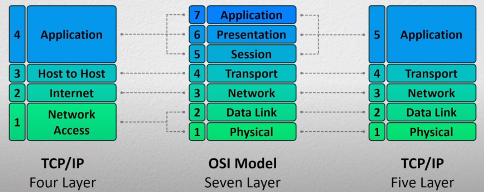
The OSI model was presented by the International Organisation for Standardisation (ISO) for how networks should be structured. Its ultimate goal is to gaurentee safe communication between two hosts that may or may not be on the same network. It has 7 layers each with a different responsibility.
- Physical layer,
- Data Link layer,
- Network layer,
- Transport layer,
- Session layer,
- Presentation layer, and
- Application layer
This separation allows for scalability, molecularity and flexibility to add or remove components. Though comes with some down sides such as
- Some layers’ functionality depends on the information from other layers, which can violate the goal of layer separation.
- One layer may duplicate lower-layer functionalities. For example, the functionality of error recovery can occur in lower layers but also in upper layers as well.
- Some additional overhead that is caused by the abstraction between layers.
Layer 1 Physical
Link to originalLayer 1 Physical
Layer 2 Data Link
Link to originalLayer 2 Data Link
Layer 2 of the OSI model concerns itself with MAC addresses and within network communication. It will have a header that stores the source and destination MAC address of the current hop within a network. These are tools that put data on or off the Physical layer. For example:
- Network Interface Cards (NIC),
- Wifi access cards, or
- Switches.
These devices all have unique MAC address.
MAC address
Link to originalMAC address
A MAC address is a 48-bit address that represent physical devices. These are made human readable by representing them as 12 hex digits (these are grouped into 2 characters and separated by - for windows : for Linux and in groups of 4 separated by a . SISCO routers and switches)
Layer 3 Network
Link to originalLayer 3 Network
This layer works with nodes identified by an IP addresses. This applies a header to a Segment with the source and destination Internet Protocol (IPv4). Devices at level 3 are:
Difference between an IP and MAC address
Difference between an IP and MAC address
For any packet we attach the source and destination Internet Protocol (IPv4). This packet may need to travel through many different networks. For each different network it will get a new layer 2 header with the MAC address of the router it entered the network on and the router it needs to leave the network on.
MAC address are really only there for a single network hop whereas the Internet Protocol (IPv4) is there for the whole journey.
Link to original
Layer 4 Transport
Link to originalLayer 4 Transport
Layer 5 Session
Link to originalLayer 5 Session
Layer 5 of the OSI model is responsible for separating out users who might be connecting through the same lower levels or the same user who is switching between different networks to connect to the same server.
Browser cookies is an example of a layer 5 technology as it allows users to switch networks without having to login again.
Layer 6 Presentation
Link to originalLayer 6 Presentation
Layer 7 Application
Link to originalLayer 7 Application
This layer determines what to do with this data. In a HTTP web server these would be the key words get, post, head ect.
The main other model of the internet is IPS model
Internet Protocol Stack (IPS) 5 layers
Link to originalInternet Protocol Stack (IPS) 5 layers
The IPS stack is a model of how communication should work over the internet. It is structured into 5 different layers:
- Application layer
- Transport Layer
- Network Layer
- Data Link Layer
- Physical Layer
It is based of the OSI model and compares as follows.
-5-layers/../../images/model-comparison.png)
Connection between OSI and IPS models
Connection between OSI and IPS models
The OSI model was originally invented when the main computers where main frames. Making layer 5 more important however in modern applications the roles and responsibilities of the last 3 layers in the OSI get very mixed and end up being combined into one in other. Some applications might not implement some of them.
For example HTTP uses cookies for layer 5, extended ASCII for layer 6, and keywords for layer 7. Whereas FTP doesn’t have a way to implement layer 5, uses the same extended ASCII for layer 6 but different commands for layer 7.
This mix of these layers is normally dependent on the protocol - so normally rolled up into one thing.
Link to original
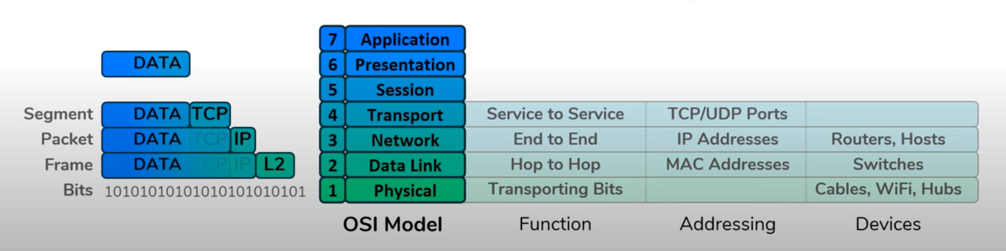
Encapsulation
Link to originalEncapsulation
Once an application has generated some data encapsulation is the process of wrapping that data with headers so it can traverse through the internet to make it to it’s destination.
Layer 4 takes the data and adds the source and destination ports to the data to make it a segment.
Layer 3 takes the segment and adds a source and destination Internet Protocol (IPv4) to make it a packet.
Layer 2 takes the packet and adds a source and destination MAC address to make it a frame.
This is moved onto layer 1 to be passed along to its destination.
The reverse process is called de-encapsulation.
Lesson 3: How do hosts talk to one another
There are two important different cases to cover.
- How host talk to one another on the same network, and
- How hosts talk to one another on different networks.
Talking on the same network
When hosts talk to each other on the same network they need 3 identifying bits of information.
- MAC address,
- Internet Protocol (IPv4), and
- Network mask (this tells the host which other hosts are on its network).
Suppose we need host A to send data to host B.
As host A is already part of the network it has the network mask already.
We will assume host A already has host B’s Internet Protocol (IPv4) through a DN entry or an act of god.
The only further information about host B host A needs is its MAC address. To do this it will need to use the Address Resolution Protocol (ARP) as discussed before.
Every host has an ARP cache that stores the MAC address against each Internet Protocol (IPv4) it knows in the network. If host B’s address is already in host A’s ARP cache it can use that to generate the layer 2 and 3 headers.
If not it will need to make an ARP request to the network. It broadcasts its IP and MAC address on the network asking for the host at host B’s IP address to respond. It does this by setting in the layer 2 header the all f’s MAC address - an address reserved for the purpose of broadcasting to the local network.
Once host B gets this ARP request it can populate its ARP cache entry for host A then send an ARP response directly back (Unicast) to host A with its MAC address.
Now with host B’s MAC address host A can now safely send the data directly to host B.
This is how computers on the same network communicate with each they use ARP to populate their ARP cache so they can directly communicate with one another.
Talking to computers on different networks
In this set up host A needs to send data to host C but there is a router in-between them. We assume host A already has host C’s IP address.
It will know this IP is on a foreign network using host C’s IP address and its own sub-net mask.
The first step for host A to send data to host C is to get it to its local router. It will know the address of that router as it will be set to the default gateway for host A. If this is the first time host A has connected to the router it can use ARP to find the routers IP address.
Host A now constructs the frame to send to the router it sets the layer 3 header using its IP address and host C’s IP address. The it sets the layer 2 header using its MAC address and the routers MAC address and sends it off unicast to the network.
At this point the router takes the frame it receives strips out the layer 2 header to get a packet then it uses it’s own ARP table to attach a new layer 2 header to send it further on. This could be directly to host C or to another router.
Lesson 4: Everything switches do to communicate within a network
Rules of a switch
These are the rules for Switching so applies to anything that can do switching.
When performing switching they only care about the layer 2 data so they don’t know anything about IP addresses - only MAC addresses.
In a switch each device connects to a different port. The switch will maintain a MAC address table that maps different ports to MAC addresses. There are then 3 operations a switch can do.
- Learn,
- Flood, and
- Forward.
When a switch gets a frame from a new host it can learn that hosts MAC address as it will be the source MAC address of that frame. So it can add this to its MAC address table.
If the switch gets a message for a MAC address it doesn’t know it will flood the network with that frame to make sure it gets to the intended host. This involves duplicating the frame and sending it on all ports that wasn’t the port the package came from.
The idea is that hosts that do not match that MAC address throw away the frame as it is not for them.
If the switch already knows the hosts port in its MAC address table it forwards that frame on to the associated port for the destination.
As this all works on layer 2 and doesn’t involve IP addresses the router on the network is just another host from the switches perspective.
Switches MAC address
Traffic going through a switch does not use a switches MAC address or IP address. However switches are hosts on that network so have an IP address and MAC address. These only get used if you are looking to connect directly to the switch to configure it.
Unicast flooding vs Brodcasts
Flooding is an action the switch takes when it does not know the port for a provided MAC address. This replicates the frame and sends it on all available ports.
Broadcast is a type of frame that has the destination MAC address set as all f’s. These will always get flooded by the switch as it will not have a port for the MAC address of all f’s.
Virtual Local Area Networks (VLAN)
Link to originalVirtual Local Area Networks (VLAN)
Multiple switches
To handle loops in the network we have to use the Spanning Tree Protocol (STP) to turn off certain connections.
Lesson 5: Everything a router does to communicate between networks
In RFC2460 Internet Protocol, Version 6 (IPv6) Specification it defines what a node, host, and router is.
Node (IPv6)
Link to originalNode
A node on a network by RFC2460 is any actor that implements Internet Protocol (IPv6).
Router (IPv6)
Link to originalRouter (IPv6)
Is any Node (IPv6) that forwards Internet Protocol (IPv6) Packets not addressed to itself. This is the definition from RFC2460.
Host (networks)
Link to originalHost (networks)
A host can have multiple meanings in the context of networks. Most broadly it means any actor that can send and receive traffic on a network. In the context of Internet Protocol (IPv6) it is a Node (IPv6) that is not a Router (IPv6).
In other words the only difference between a router and a host is that a host will drop a packet not matching its own IP address whereas a router will do its best to get that packet to its home.
A router keeps a table of all networks it knows about in its routing table. Different networks are identified by the part of the IP space associated to that network. The router will bind these different network spaces to interfaces of the router.
Unknown packet address
If a router gets a packet it does not know the address of it will just drop that packet.
Routing
Link to originalRouting
The process of routing is getting a packet the network associated to its IP address. To do this all routers store a routing table which maps the tuple of an IP address and a network mask to either a interface or a IP address.
There are two types of routing Intradomain routing, how routers exchange information within the same Autonomous system (AS), and interdomain routing how routes get shared between Autonomous system (AS).
There are 3 ways a router can populate its routing table
- Directly connected: This is for networks directly connected to the router. It adds an entry for that networks and the interface of the router it is connected to.
- Static route: This is a route that has been manually configured on a router. Instead of an interface it will have an IP address to forward that packet on to.
- Dynamic routing: This is the same in structure to the static rout but instead of being manually added this gets populated by routers sharing known addresses with one another.
This table might grow very large but routers use route summarization to keep the tables shorter.
Once a router has been configured when it receives a packet it looks at its layer 3 header containing the destination IP address. It compares that again the known address, using the network mask and finds the most precise match (matching on the longest network mask) then forwards it to that interface or IP address.
There are many different Dynamic routing protocols RIP, OSPF, BGP, EIGRP, IS-IS, ect They differ in how they discover new routers, what addresses they share, and how they share thous addresses.
Difference between an ARP table and a Router table
As routers have IP addresses on the networks associated to their interfaces they therefor have to have ARP tables for these networks.
The main difference between ARP tables and router tables is that ARP tables always start empty and can be fully populated through ARP. If the router gets a frame it doesn’t have an ARP entry for it will use ARP to discover it - whereas if a router gets a packet it doesn’t have a routing entry for it will drop that packet.
Hierarchy helps with scaling
If you use a tree like network to connect routers the longest path grows like
With the entries in the routing table the subnet mask indicates what part of the IP address you need to match on. For example the routing table may look something like
| IP address | Subnet mask | Interface |
|---|---|---|
| 10.40.55.0 | 24 | R1 |
| 10.20.0.0 | 16 | R2 |
the first entry would say any IP address matching the first 24 bits or the first 3 decimals of the IP address go here whereas the second entry says any address matching the first 16 bits or 2 decimals then go here. The second entry is called route summarization. It is actually referring to a lot of subnets but groups them all index one entry as the first step is always to go to a single router. This can only be done if you arrange your IP addresses in a hierarchical manner.
You can set a default route - this is one that matches on 0 bits. Then instead of dropping any unknown address you instead send it to the default route.
Matching criteria
If you have a default gateway then it will match with all addresses which might cause a conflict. By default the more specific a routing entry the higher priority that rule. Though rules can get more complicated than this.
Lesson 6: Protocols
Protocol: Set of rules and messages that form an Internet standard.
Some were already described above. Such as ARP (RFC 826).
File Transfer Protocol (FTP)
Link to originalFile Transfer Protocol (FTP)
This is a simple file transfer format which starts with the client sending a RETR message with the file name to get a file from a server.
Simple Mail Transfer Protocol (SMTP)
Link to originalSimple Mail Transfer Protocol (SMTP)
This is the protocol mail servers communicate with users.
Hyper Text Transfer Protocol (HTTP)
Link to originalHyper Text Transfer Protocol (HTTP)
The underlying protocol for web-servers.
Secure Socket Layer (SSL)
Link to originalSecure Socket Layer (SSL)
Transport Layer Security (TLS)
Link to originalTransport Layer Security (TLS)
The is an encryption protocol. It used to be called SSL.
Domain Name System (DNS)
Link to originalDomain Name System (DNS)
The domain name systems main function is to translate a human readable domain name into an IP address. It is in essence a massive distributed database across many server. This distributed database uses different DNS records and a hierarchy of servers.
- Root DNS servers: There are 13 mainly located in North America which are a network of replicated servers.
- Top level domain (TLD) server: These are responsible for top level domains such as .com, .org, ect.
- Authoritative servers: An organisations DNS server that control their domain.
- Local DNS (LDNS) servers: This can be owned my users or ISPs and act as a proxy to the root servers.
When querying DNS servers requests can either be iterative meaning that the host that sends them keeps getting back another location to go to or recursive which means the host requested for the information goes directly to the next server. An example of a typical request can be seen below.
DNS servers also offer other services such as:
- Mail server,
- Load distribution,
- Certificate authorisation,
- Others that can be found in the DNS records.
Dynamic Host Configuration Protocol (DHCP)
Link to originalDynamic Host Configuration Protocol (DHCP)
To connect to the internet you need 4 bits of information:
- Your Internet Protocol (IPv4),
- Your network mask,
- The default gateway of your local network, and
- The Domain Name System (DNS) server you will use.
The DHCP will provide you all the above information once you connect to a new network. When you first join a network you send DHCP discover message and will be provided with all your information.
Preparation questions
- What is a “protocol”? What are some of the most well-known and used protocols?
A protocol is a set of messages and rules that are an internet standard. They can be found defined in RFC’s. Some popular protocols are ARP, HTTP, TLS, and DNS.
- What is an ISP? What is an AS?
Internet Service Provider (ISP)
Link to originalInternet Service Provider (ISP)
An internet service provider (ISP) is a company that provides individuals and organizations access to the Internet and other related services.
There are different size internet service providers and the lines between them are not always clear:
- Global (Tier 1) ISP: These form the backbone of the internet.
- Regional (Tier 2) ISP: These offer services in one particular area.
- Access (Tier 3) ISP: These offer access to individuals to the internet.
Autonomous system (AS)
Link to originalAutonomous system (AS)
An Autonomous system (AS) is a collection of IP addresses with a common prefix all controlled by a single administrative entity or domain.
- What is the OSI layer model? What is the primary responsibility of each layer?
The Open System Interconnection model is the 7 conceptual layers of how connected systems work.
- Physical: Cables and transportation of data.
- Data Link: Devices that move data on and off the physical layer. Identifies actors by MAC addresses.
- Network: Devices that work as the ultimate destination for data within a network. Uses IP addresses to distinguish actors.
- Transport: The passes data going to the same host to different processes. This uses ports to distinguish entities.
- Session: This allows users using the same process to be distinguished.
- Presentation: This determines how the data should be interpreted.
- Application: How the data will be used to run commands.
- How does the layered architecture of the internet allow fundamentally different technologies (such as WiFi vs. Ethernet) to be used together?
It established clear separation of concerns and the interfaces in which the operate by. For example for ethernet or Wifi as long as the data has been encapsulated properly these Physical layers are only responsible for getting data to the next entity in the network.
- What is the client-server model? What is the peer-to-peer model? What are the strengths and weaknesses of each?
Client-Server model
Link to originalClient-Server model
The client-server model is a distributed application structure with two roles. There are servers providing resources and clients requesting them. For example, a web-server follows the client server model. The user of the browser is the client and the server providing web-pages is the server.
Advantages
- A service that is centrally managed is easier to monitor.
- Easier to apply access controls and security to the system.
- With a centralised system you can gaurentee data integrity more easily.
Disadvantages
- Single point of failure if the server goes down.
- Higher start up cost as you require the infrastructure in the first place.
- Scaling can become complex as the server can become a big bottle neck.
Peer-peer model
Link to originalPeer-peer model
The peer-to-peer model is a decentralised application architecture which has each participant being both consumer and provider of resources. Each peer offers some of its resources up to the network for other peers to use without central coordination. An example of this is Torrent file sharing.
Advantages
- Naturally scales as more people use the system.
- Cost effective as there is no centrally managed servers.
- Fault tolerant as any number of nodes going down does not stop the system working.
Disadvantages
- Security challenges as no central authority is dictating who is allowed into the network.
- Can not guarantee data integrity of assets on the network.
- Hard to manage and monitor as there is no central place collecting logs.
- What is a port (number)? How is it used?
A port number is how Layer 4 distinguishes different applications. It is used to separate up messages going to the same host.
- What’s the difference between a well-known port number and an ephemeral port?
Port
Link to originalPort
A port is just a number that the host associates to an application. Ports break down into 3 groups
- 0-1023 are well known ports,
- 1024-49151 are user or registered ports, and
- 49152-65535 are ephemeral ports.
Well known ports are used for system processes and protocols. For example port 80 is used by webservers for HTTP.
Registered ports are used for user applications that need a port to work off of.
The ephemeral ports or dynamic ports are used for private or temporary uses for example to connect to a web browser and receive a web page.
- What is TCP? What is UDP? What are some of the major differences between them?
Transmission Control Protocol (TCP)
Transmission Control Protocol (TCP)
The transmission control protocol is a layer 4 protocol that allows for multiplexing and a duplex communication channel. It is defined in RFC793. This is a connection orientated protocol which establishes a connection with TCP 3 way handshake and closes connections with the TCP connection teardown. This gaurentees the following features.
- reliability: every message will be received and acknowledge or it will be redelivered,
- ordered delivery: messages have a sequence number and will only be parsed to the Application layer in order,
- error checking: Checksum in layer 4,
- Transmission control in TCP:
- Flow control: allow the receiver to dictate how many message it can buffer.
- Congestion control and fair usage: will use connection probing to determine a safe and fair transmission rate.
The TCP header has the following fields:
- Source port,
- Destination port,
- sequence number: the sequence number of the first data octect, this has a special role in the TCP 3 way handshake,
- Acknowledgement number: the next sequence number the receiver is expecting to get,
- Data offset: the number of 32 bit words in the TCP header,
- Reserved: set to all 0’s,
- control bits: these are 0 or 1 for the following 6 fields Urgent, Acknowledgement, Push, Reset, Synchronise, and Finish.
- Window: The number of data octets number of data octets the sender of this segment is willing to receive.
- Checksum: Checksum in layer 4,
- Urgent pointer,
- Options, and
- Padding to make the header a multiple of 32 bits.
Flow control in TCP
Link to originalSuppose [[Host (networks)|host]] A is transmitting data to [[Host (networks)|host]] B. When this starts up [[Host (networks)|host]] B will reserve some amount of memory to buffer unprocessed packages. Lets say it can fit `RcvBuffer` bytes. Then it keeps track of `LastByteRead` and `LastByteRecieved`
/../../images/tcp_header.png)
User Datagram Protocol (UDP)
Link to originalUser Datagram Protocol (UDP)
/../../images/udp-header.png) This tends to be used in applications that are latency sensitive or have small number of messages to send.
This tends to be used in applications that are latency sensitive or have small number of messages to send.- If you were developing a brand new application layer protocol, what aspects of TCP would make it more appealing to use? What aspects of UDP would make it more appealing to use?
I would use TCP if I wanted to gaurentee integrity of the data and didn’t care about latency whereas I would use UDP if I wanted a fast connection where packet replay was not important.
- What is a socket? How is it used?
Socket
Link to originalSocket
A socket is the collection of 3 bits of information:
- A transport protocol such as TCP or UDP,
- An Internet Protocol (IPv4), and
- A port.
They are used by applications to get send and receive data. This is the PO box for this application on the internet.
- Can you generally describe how HTTP works in an example (how the HTTP request is initiated, how the webserver receives the request, how the content is returned, etc.)?
Yes I think so but that is a lot of writing.
- What is an IP address? How is it different than a MAC Address?
An IP address is the unique identifier for a host. This works for hosts that are not not the same network. This will be added to the message at Layer 3 and is responsible for checking the message is going to the correct host. MAC addresses are encapsulated at layer 2 and are only responsible for getting the frame to the correct host within a network.
- What is a switch? What is a router? What are the major differences between the roles that they play in a network, classically?
Switches are responsible for getting data between hosts on the same network. The have an ARP table and can do 3 operations, learn, flood and forward. These allow for the switch to learn about new hosts that are connected to its ports and find their MAC addresses. This device only cares about the layer 2 information of the message.
Routing on the other hand is responsible for getting packets to hosts that are not on their network. The maintain a route table that informs them about the IP addresses it knows where to route packets to. This operates on the Layer 3 information of the packet.
- What is a default gateway
The default gateway is the address of the main router in that network it is IP address that hosts add the MAC address of if the IP address is not in this network.
- What happens to a message as it gets sent across a network, as far as encapsulation and protocol headers?
Suppose we have a message we need to send to an application first we encode that information using the specification of layer 6 of the target application. We add headers to identify this user session in layer 5. Then we add the randomly assigned source port of the application sending the data and the destination port of the application we need to send the information to. Now we add the IP address of the machine sending the data and the IP address of the machine we want to send the data to. Then we use that IP address and the subnet mask to determine if the machine is on our network or a foriegn network. Then we either uses its address or the default gateway’s address to look a MAC address of the next hop in the network in our ARP table - if we don’t have it we use ARP to determine that MAC address in the network.
- What is DNS? At a high level, how does it work?
Domain Name Service map domain names to IP addresses. When connecting to a domain name like www.example.com first you go to your domain name provider to look up the associated IP address then once you have done that you can send the message to the server. Note this doesn’t resolve the port of the application this would need to be known before hand. Lots of standard protocols use default ports.